As far as practice excersizes go a basic bearing is a great one to learn basic concpets on OpenSCAD. This tutorial takes a differenct approach and uses the 2d Subsystem as a kind of “Sketcher”.
The full code is at the end of the article but if you just want the goods you can go to the Models tab and get the code there.
The Model
We will be basing our bearing off the famous 802zz Skate Bearing. You can find a drawing of that model over at mathcodeprint.com
Or purchase a licensed copy at : https://www.teacherspayteachers.com/Product/Engineering-Diagram-for-608zz-Bearing-Basic–5719806
Adding the Inner Race.
The inner race will be made simple by subtracting a circle from a cube.
First lets make the main body of the inner race.
Add add square where x = 7 and y = 2, then translate that square 5 units on the X axis. The inner Radius is 4 but because we turn centering on we need to add 1 to offset half the thickness of the square. Turn centering on for the square.
translate([5, 0, 0]){
  square([2, 7], center=true);
}
Press F6 to Render the Square
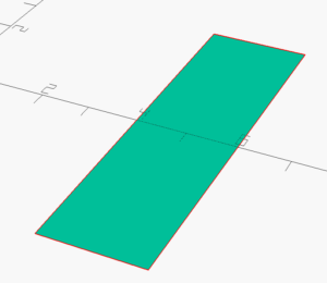
Now add a circle ( which will cut the ball pattern ). We will use a radius of 1.98. Move that circle by 7.56 units on the X-Axis
translate([5, 0, 0]){
  square([2, 7], center=true);
}
translate([7.56, 0, 0]){
  circle(r=1.98);
}
Press F6 to Render the Square and the Circle
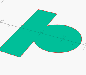
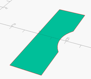
Place both commands inside a difference() {}
  difference() {
    translate([5, 0, 0]){
      square([2, 7], center=true);
    }
    translate([7.56, 0, 0]){
      circle(r=1.98);
    }
  }
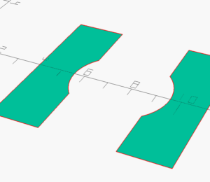
We will repeat the same procedures but with values suitable for the outer race.
  difference() {
    translate([10, 0, 0]){
      square([2, 7], center=true);
    }

    translate([7.56, 0, 0]){
      circle(r=2);
    }
} 
That is all you need to create the Inner and Outer Race. Now we can use rotate_extrude to add the third dimension.
Place all your code so far inside a rotate_extrude(){}
So both the Inner RAce and the Outer Race will be within the brackets of the rotate_extrude. You code should look something like this. OpenSCAD does not see the extra whitespace, like tabs, the formatting here is just for clarity.
rotate_extrude(){
    //Inner Race
    difference() {
      translate([5, 0, 0]){
        square([2, 7], center=true);
      }
      translate([7.56, 0, 0]){
        circle(r=2);
      }
     }
     //Outer Race
     difference() {
       translate([10, 0, 0]){
         square([2, 7], center=true);
       }
      translate([7.56, 0, 0]){
        circle(r=2);
      }
    }
}
If you render now you outer in inner race will be 3d !
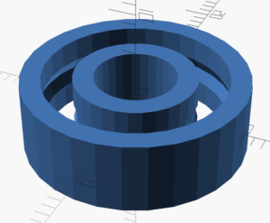
Now lets add bearing balls
The bearing balls are easier to complete in 3d so we will start with a sphere that has a radius of 1.98 ( Just a tiny bit smaller than the Raceways ). We will move that ball into position by translating it along the x to 7.56 To make the sphere actually resemble a sphere lets set $fn to 25.
translate([7.56, 0, 0])
    sphere(r=1.96, $fn=25);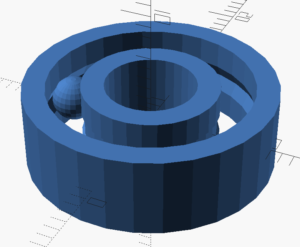
It may appear as if the sphere is intersecting the raceways. That effect is due to the low number of polygons used to render the raceways. We will fix that last.
The last modeling step is adding the other balls. There are seven in the 608xx bearing. So we will add seven. Add the rotate command and for loop as shown. This will add one sphere at each of 7 positions moved through by the for loop.
!for (i = [1 : 1 : 7]) {
  rotate([0, 0, (i * 360/7)]){
    translate([-7.56, 0, 0])
        sphere(r=1.96, $fn=25);
    }
 }
Use the Exclamation Point, in front of the for loop to see only the seven balls. Then press f5 to get a preview.
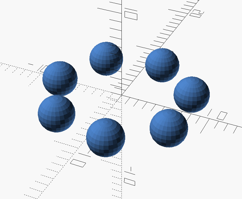
Finally , lets clean it up a bit. Remove the Exclamation point and place $fn=50; at the beginning of your code. Press F6 to render the final model.
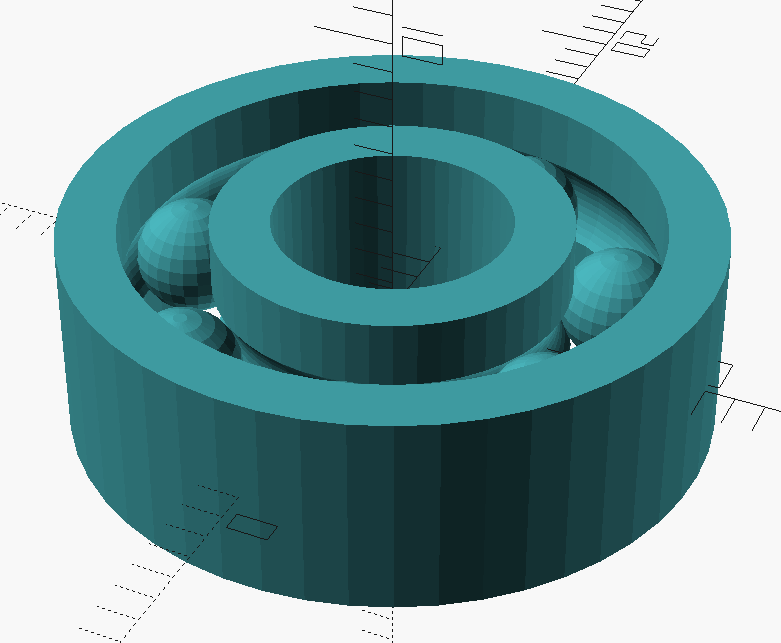
Here is the full code if you would like to try it:
$fn=50;
rotate_extrude(){

    difference() {

    translate([5, 0, 0]){
      square([2, 7], center=true);
    }

    translate([7.56, 0, 0]){
      circle(r=2);
    }

  }
  difference() {
    translate([10, 0, 0]){
      square([2, 7], center=true);
    }

    translate([7.56, 0, 0]){
      circle(r=2);
    }
  }
}
for (i = [1 : 1 : 7]) {
  rotate([0, 0, (i * 360/7)]){
    translate([-7.56, 0, 0])
        sphere(r=1.96, $fn=25);
    }
 }
